
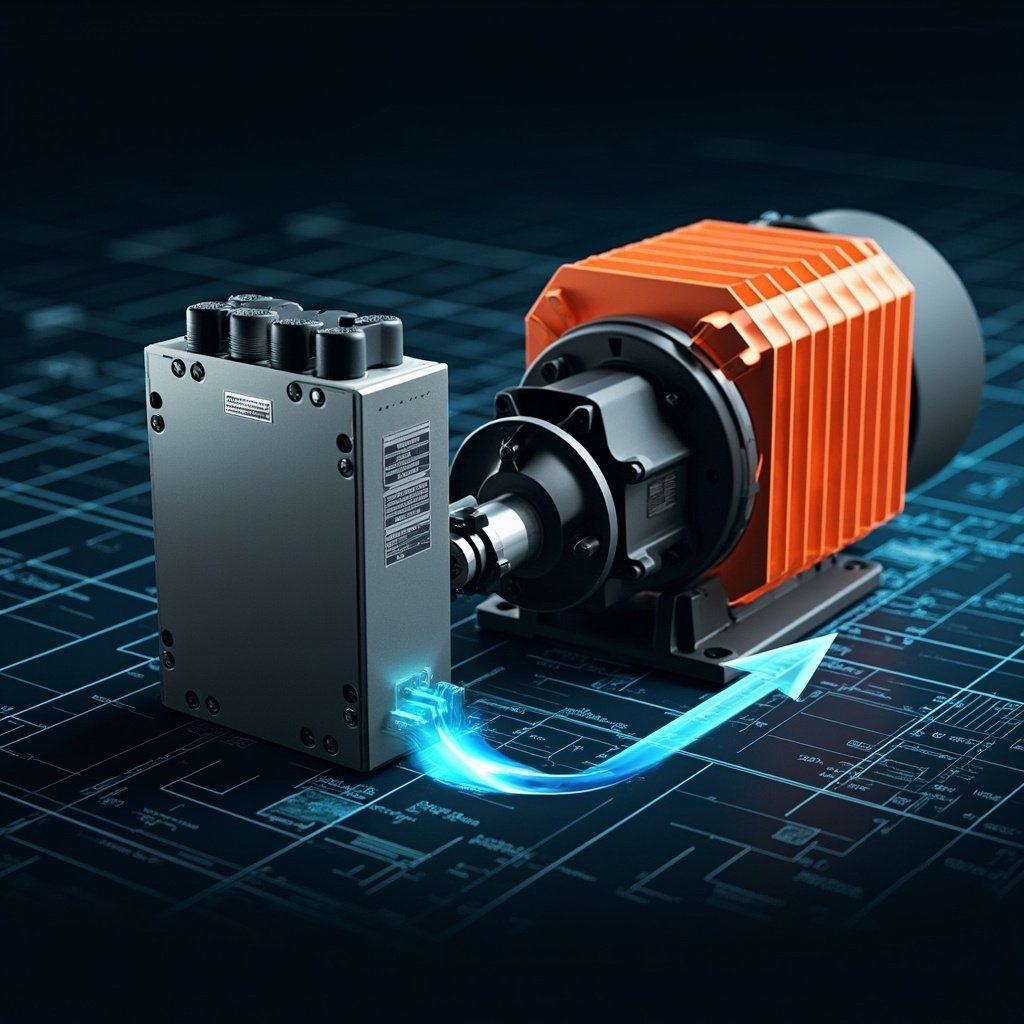
Variable Frequency Drives (VFDs) are essential components in modern industrial automation and motor control systems. They enable precise speed regulation, energy savings, and improved process control. However, when decelerating a motor, the VFD must dissipate the regenerative energy generated by the rotating motor acting as a generator. This is where braking resistors become critical. Understanding VFD braking resistor calculation is essential for engineers, technicians, and system designers who want to ensure safe, reliable, and efficient motor deceleration. In this comprehensive guide, we will walk you through the entire process of calculating the appropriate braking resistor for your VFD application, covering formulas, practical examples, and key considerations that will help you make informed decisions.
Understanding VFD Braking Resistors and Why They Matter
When a VFD reduces the frequency output to slow down a motor, the motor’s rotor continues to rotate at a speed higher than the synchronous speed determined by the new frequency. In this scenario, the motor operates as a generator, converting kinetic energy into electrical energy. This regenerated energy flows back into the VFD’s DC bus, causing the voltage to rise. If left unchecked, this voltage increase can damage the drive’s internal components, trigger overvoltage faults, or cause unexpected system shutdowns.
A braking resistor is connected to the VFD’s DC bus through a braking chopper or transistor. When the DC bus voltage exceeds a predetermined threshold, the braking chopper activates, routing the regenerative energy through the resistor where it is converted into heat and dissipated. This process protects the VFD, ensures smooth deceleration, and prevents costly downtime and equipment damage. Without proper calculation and selection of the braking resistor, systems can experience premature failures, inconsistent braking performance, and safety hazards.
Key Parameters for VFD Braking Resistor Calculation
Before diving into the calculation itself, you need to understand and gather several critical parameters that influence the braking resistor selection. These parameters form the foundation of an accurate and reliable calculation.
Motor Specifications
- Motor Power (P): The rated power of the motor in kilowatts (kW) or horsepower (HP). This is typically found on the motor nameplate.
- Motor Voltage (V): The rated voltage of the motor, usually 460V, 380V, or 230V for three-phase motors.
- Motor Speed (N): The rated speed in revolutions per minute (RPM), typically 1800 RPM or 3600 RPM for standard industrial motors.
- Full Load Amps (FLA): The rated current drawn by the motor at full load conditions.
Braking Parameters
- Deceleration Time (t): The desired time to bring the motor from full speed to zero or a lower speed, measured in seconds.
- Initial Speed (N1): The speed before deceleration begins, usually the motor’s rated speed.
- Final Speed (N2): The target speed after deceleration, which may be zero or a lower operating speed.
- Load Inertia (J): The total inertia of the motor rotor and the connected load, measured in kg·m². This is crucial for accurate calculations in high-inertia applications.
- Braking Torque (Tb): The torque required to decelerate the load within the specified time.
VFD and System Parameters
- DC Bus Voltage (Vdc): The internal DC bus voltage of the VFD, which is approximately 1.35 times the incoming AC voltage for standard drives.
- Braking Chopper Voltage Threshold: The voltage level at which the braking chopper engages, typically set 10-15% above the nominal DC bus voltage.
- Duty Cycle: The percentage of time the braking resistor will be actively dissipating energy during a given period.
The Fundamental Braking Resistor Calculation Formula
The core of VFD braking resistor calculation revolves around determining the resistance value and the power rating of the resistor. Let’s examine the essential formulas that govern this process.
Calculating Braking Torque
The braking torque required to decelerate a load within a specified time is calculated using the following equation:
Tb = (J × ΔN) / (t × 9.55)
Where:
- Tb = Braking torque in Newton-meters (N·m)
- J = Total moment of inertia (kg·m²)
- ΔN = Change in speed (N1 – N2) in RPM
- t = Deceleration time in seconds
- 9.55 = Conversion constant (relates angular velocity to torque)
Calculating Braking Power
Once you have determined the braking torque, you can calculate the braking power using:
Pbrake = (Tb × N1) / 9550
Where Pbrake is the braking power in kilowatts (kW) and 9550 is a conversion constant that accounts for the relationship between torque, speed, and power.
Calculating Resistance Value
The resistance value of the braking resistor is determined by the VFD’s DC bus voltage and the maximum current the braking chopper can handle:
Rmin = (Vdc²) / (Pmax × 1000)
Alternatively, if you know the maximum braking current (Ibrake):
R = Vdc / Ibrake
Where Vdc is the DC bus voltage, typically 1.35 × Vac (for example, 1.35 × 460V ≈ 621V DC for a 460V system).
Calculating Power Rating
The power rating of the braking resistor must be sufficient to handle the average braking power while accounting for the duty cycle:
Prated = Pbrake × √(Duty Cycle)
For applications with frequent braking cycles, the power rating should be significantly higher than the calculated average power to prevent overheating and premature failure.
Step-by-Step Calculation Example
To illustrate the VFD braking resistor calculation process, let’s work through a practical example step by step.
Given Parameters
| Parameter | Symbol | Value | Unit |
|---|---|---|---|
| Motor Power | P | 30 | kW |
| Motor Voltage | V | 460 | V |
| Motor Speed | N | 1780 | RPM |
| Total Inertia | J | 2.5 | kg·m² |
| Deceleration Time | t | 3 | seconds |
| Speed Reduction | ΔN | 1780 | RPM |
| DC Bus Voltage |